The Wave Function Collapse (WFC) algorithm is typically used to procedurally generate a 2D bitmap/tilemap using one of two models:
- Overlapping model: Taking in a similar smaller map it is trying to "imitate"
- Simple tiled model: Taking in a list of tiles and adjacency rules.
I've been working on implementing the latter model in the Godot Engine to figure out how to procedurally generate a 3D level. Since this is the 3D implementation of WFC, I based it on the Model Synthesis algorithm.
In the most simple terms, the algorithm works using these general steps:
Initialize a grid of N x M x O tiles, with each tile containing all the possibilities of the tiles it can be.
While there are uncollapsed tiles in the grid:
	Select an uncollapsed tile from the grid and randomly "collapse" it to one of its possibilities.
	Propagate the effects of the collapse of that tile to the rest of the grid.
Originally, I had cobbled together a version of WFC from watching online tutorials and reading pseudocode on the way the algorithm would work. My starting point was Martin Donald's explanation comparing WFC to solving a Sudoku puzzle. This gave me a good intuitive starting point to figure the algorithm out. But intuition was not enough. This algorithm was a bit of a monster.
Prologue: The Building Blocks
Before even getting to WFC, there was another problem in front of me: tileset generation. I could have gotten a tileset from somewhere else, but that meant I still needed to create the adjacency rules so that WFC would know how tiles fit together. So I started by working on my own simple tileset using Calame321's tutorial which got me used to modeling in Blender with a grid as well as figuring out how to make tiles that are meant to be connected.
I had originally attempted to just model tiles willy-nilly but it turns out that modeling for a tilemap and creating general 3D models to be used in environments does not follow the same process. None of the models were solid. After all, those wasted vertices that would never be seen as they would be hidden inside the level when it was created. A sparse vertex count also helped with the next stage of this project: creating the adjacency data for the tiles.
For WFC to work, the algorithm needs to understand which tiles are allowed next to other tiles. Creating this list manually would be exhausting, especially when you consider that most tiles can be rotated 4 ways. Automating the process would be nice. Donald's explanation of Model Synthesis' technique uses a "socket label" system. That is, for each of the six sides of a model, we label it using a socket number. Any models that have the same sockets have their sockets labeled with the same number. If a socket is symmetrical, its label is appended with the letter S, otherwise, its label is appended with the letter F if it is the flipped version of the socket. Once all the sockets are labeled, we can automatically generate adjacency lists for each piece by matching sockets together. Additionally, instead of copying each model 3 times to have 4 possible rotations, we can create "prototype" objects in our code which list a tile's mesh and rotation. Instead of matching the sockets of models, we would be matching the sockets of prototypes. When the game engine would instantiate the models, it would use the prototype data to figure out which mesh to instantiate and at which rotation.
Sounds simple enough but for someone who:
- Had not coded in Python for a while
- Was a bit of an amateur at 3D modeling in Blender
- Had never scripted in Blender
- Was not aware of the discrepancies between Blender and Python's floating point values
this was a bit of a challenge. Of course, I could have labelled the sockets on each mesh manually. But Donald's video recommended doing it with code, and for a large tileset, I couldn't imagine doing it by hand. So I learned a few things the hard way:
- A straight line containing 2 vertices (0,1,0) and (2,1,0) might coincide with a straight line containing 3 vertices (0,1,0), (1,1,0), and (2,1,0), but they will not be detected as matching sockets as the vertices are different. My options included either:
- Finding a way to detect that the extra vertex in one set was covered by the other set somehow using math. This meant checking for multiple corner cases.
- Making sure the vertices on the tiles matched exactly.
- Going for Option 2 was simpler. It made me model while aware of the fact that all tiles must be modeled using the same number of subdivisions. However, this came with the caveat that if any new tile required more subdivisions, all the rest of the tiles would need to be subdivided the same way. I learned this when I added my own stair tile to the tileset and watched all the adjacency rules break because of the added subdivisions.
- Never use == when comparing two floating point values. Imagining the extent of the pain I went through while not knowing this will be left as an exercise to the reader.
- Blender and Python store floating point values with very different precisions. Use a much larger epsilon value than you think you'd need. Like 0.001 or even 0.01 and keep this in mind while subdividing and modeling.
- Sometimes when snapping to a vertex with a 0.0 component, Blender will store a -0.0. So, uh, make sure to fix that.
Nevertheless, she persisted. The prototype adjacency data was now organized nicely in a neat JSON file, ready to be fed to Godot. Each prototype included:
prototype_name : string; // A combination of the mesh name and the rotation value
mesh_name : string;
rotation : number; //0-3 (in increments of 90 degrees)
// Neighbors are listed using their prototype names
possibleNeighborsXPos : string[];
possibleNeighborsYPos : string[];
possibleNeighborsZPos : string[];
possibleNeighborsXNeg : string[];
possibleNeighborsYNeg : string[];
possibleNeighborsZNeg : string[];
An Omen
For anyone who is familiar with Blender and/or Godot, you might have noticed a potential problem with this setup:
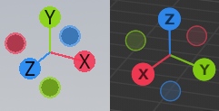 Since I was not too familiar with Godot at the time, I will leave this here as an omen for what is to come and continue with discussing how I implemented WFC in my blissful ignorance.
Act 1: The Madman's Attempt at Wave Function Collapse
Part 1: The Grid
I decided to make a class for the grid and a class for the cells. I stored the cells in the grid using a Dictionary:
public class WFCGrid
{
	private Dictionary<Vector3, WFCCell> _cellGrid;
	//...
}
Why not use a multi-dimensional array? It's because I needed to store references to the keys of this dictionary in another structure which would determine which would determine which cells I would be collapsing. I thought I was so smart for planning ahead.
Part 2: Collapsing
What makes Wave Function Collapse unique compared to other implementations of texture or model synthesis is its use of the Entropy heuristic.
The way I understand it, entropy measures dramatic tension. If you chose to collapse a cell with a high entropy value to one of its possibilities, chances are you won't be able to guess what it'll collapse to. On the other hand, a low entropy cell is one where you're less likely to be surprised by the outcome. At this point, I took entropy as the number of possibilities a cell could collapse to.
My "research" showed that the best cells to collapse were the cells with the lowest entropy. Makes sense. It was probably best to collapse the cell with 2 valid options instead of the one with 30, lest the former cell lose all its possibilities later on. After all, that would lead to a dreaded contradiction. So here's where I thought I was a genius:
Store the coordinates of the cells in a PriorityQueue, where the priority was the cell's entropy value!
private PriorityQueue<Vector3> _entropyHeap;
You could flip the entropy values to the negatives so the item with the lowest entropy would be at the front of the queue. When you want to collapse a cell, you can just pop the queue and have your next cell be waiting for you at the front in O(logn) time!
Part 3: Propagating
This was the hard part. Now that I had a collapsed cell, I needed to propagate its effects to the grid. Originally, I had the cells themselves handle propagating by calling the Propagate() function and removing invalid possibilities from each other. I quickly came face to face with the Recursion Devil.
Instead, I decided to let the grid class take care of the propagation for me. I introduced this bad boy to the class and made it so any cell that got collapsed would be pushed in.
private Stack<Vector3> _propagationStack;
After collapsing a cell, the Propagate() function would be called. It looks at the neighbors of the top element of the stack and removes prototypes in them that are no longer viable. If any changes are made to a neighbor, it gets pushed onto the stack. Loop until the stack is empty.
Now that the propagation is complete, you just keep collapsing and propagating over and over until no cells can be collapsed anymore. Except...
Part 4: Oh.
If propagation changes the number of viable prototypes in a cell, it changes the entropy of the cell. That means that the _entropyHeap needs to modify the priority of its elements. A C# PriorityQueue cannot modify the priority of its elements.
After banging my head against the wall for a while, hoping for the promises of a PriorityQueue to be broken somewhere in the documentation, I ended up just going for ol' Reliable:
private List<Vector3> _entropyHeap;

// ...

public void RefreshEntropyHeap() {
	_entropyHeap.Sort(delegate(Vector3 a, Vector3 b) {
		return _cellGrid[a].Entropy.CompareTo(_cellGrid[b].Entropy);
	});
}
As I write this, I note that the original implementation of WFC does not even store the entropy values in a list, opting to just scan the grid for the cell with the minimum entropy. If only I had checked earlier.
So now the order of operations was consolidated:
1. Make the Grid
2. While there are cells to collapse
	1. Collapse a cell
	2. Propagate Changes
	3. Refresh the entropy "Heap"
I run the algorithm, sparkles in my eyes, and...
Part 5: Chekov's Gun Fires
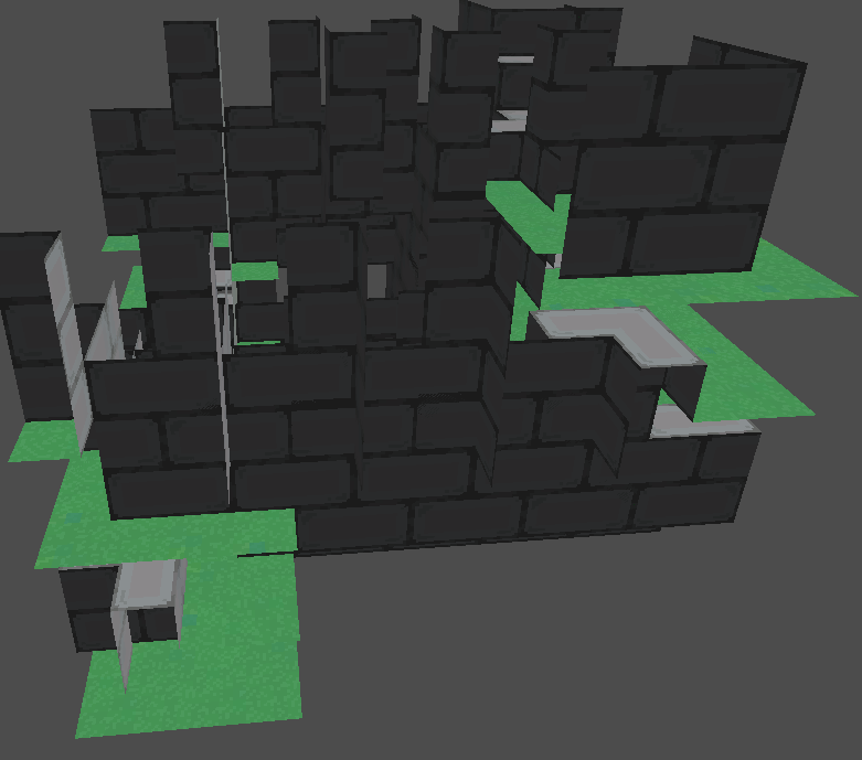 Remember the Omen?
After a long wild goose chase, involving implementing a function that stepped through the collapse and showed me each cell it collapsed one-by-one, I realized the coordinates of the cells were switched and that Godot was spawning them in the wrong locations. So I wrote a function that swapped the coordinates that were influenced by Blender's system to the Godot system. And finally, it looked...
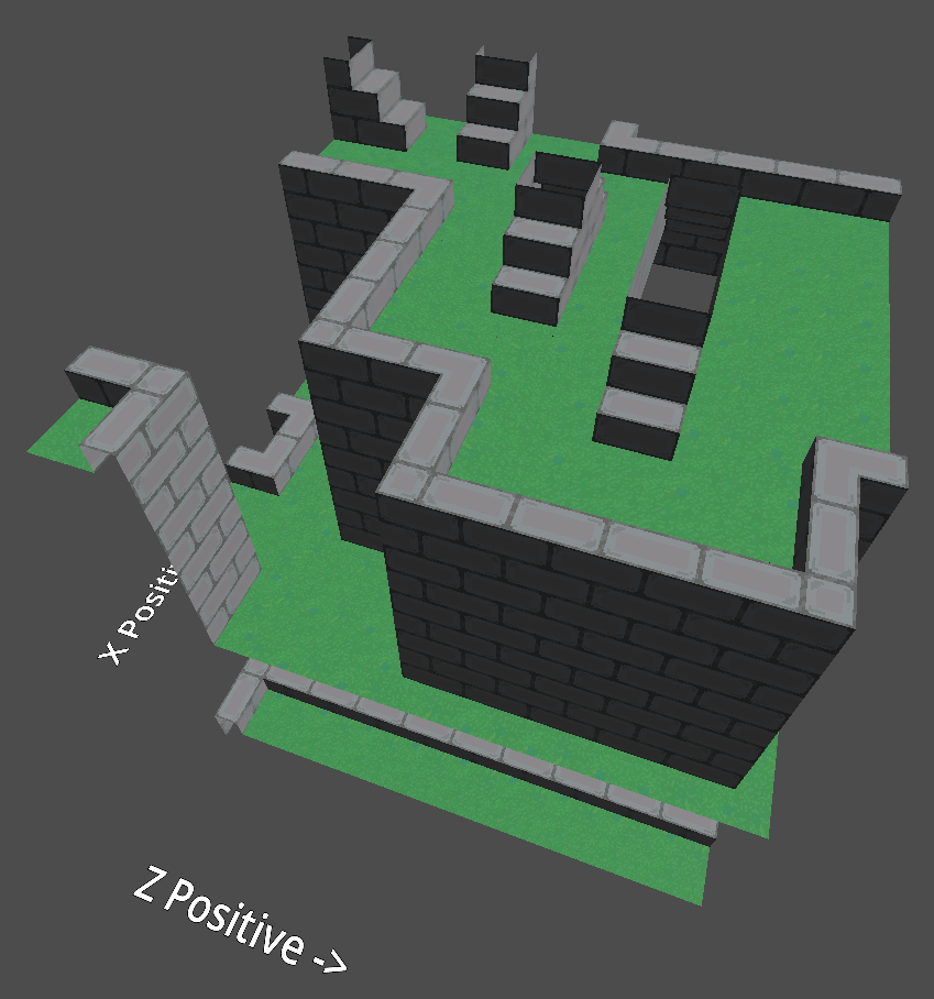 ...like it could use some work.
Sure, all of the pieces were technically allowed to be where they were. But I didn't like how the model split into floors. Unfortunately this was an issue introduced by the fact that my flat ground prototype was required to have empty space under it and over it, meaning you could have a totally valid set of flat floors. So I had an improvement I needed to introduce.
Part 6: Initial Conditions
Originally I hard-coded initial conditions into the algorithm by making it set some tiles to ground and some tiles to empty space from the start. I then decided to create another JSON file for restriction data, allowing you to specify ranges of cells and lists of prototypes they were allowed to be. The conditions would be deserialized into a Restriction class with the followed elements:
xRestrictionMin : number;
yRestrictionMin : number;
zRestrictionMin : number;
xRestrictionMax : number;
yRestrictionMax : number;
zRestrictionMax : number;

validTilesForRestriction : string[];
Before the WFC algorithm even runs, the ranges of cells specified in these restriction classes would have their possibility sets culled to contain only the prototypes listed in the validTilesForRestriction array. And voila!
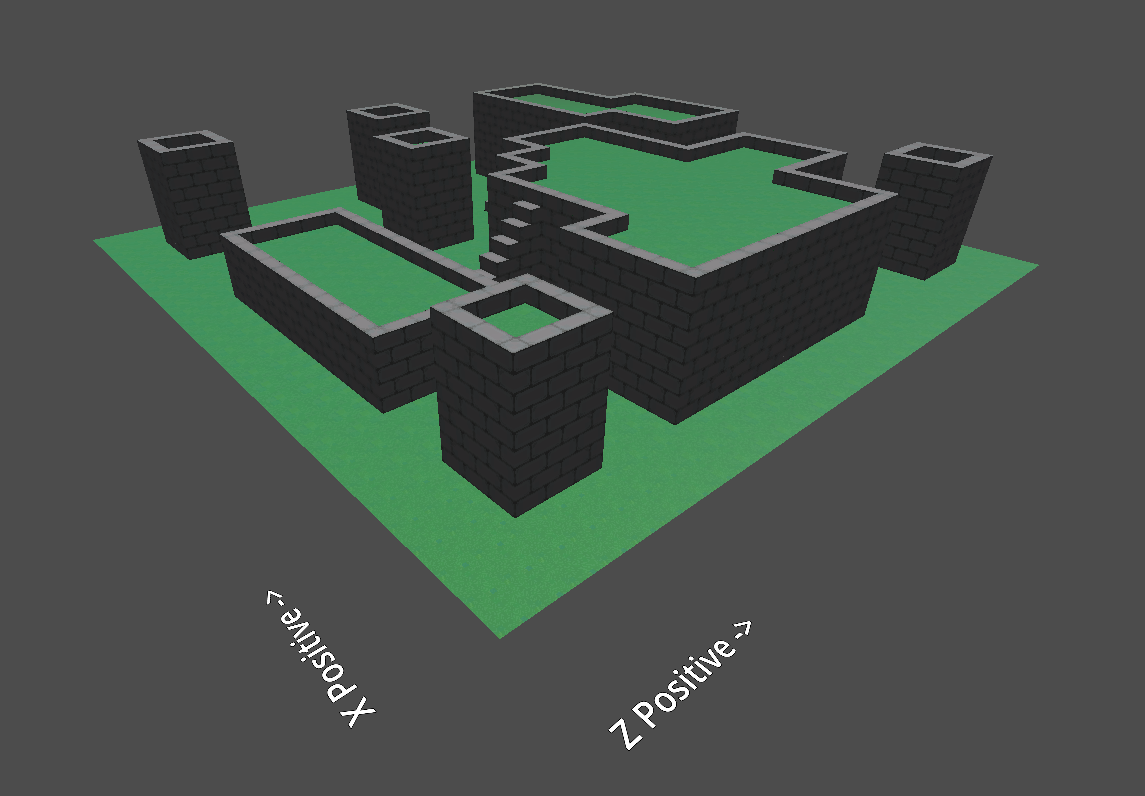 It WORKS! But now came the next question: How do I tell this algorithm what I want to see more?
Part 7: Weights
When I watched Donald's video, weights were left as an exercise for the viewer. I didn't realize adding weights would make me tear this algorithm down and build it up again. (This is an exaggeration, but it's what it felt like.)
Adding weights had to happen back in Blender, where I had introduced some metadata to the models allowing me to tell Blender what weight to give that model's prototypes. The weights were then added to the prototype data by my Blender script. It was time to put them to use, which meant I needed to research Weighted Random Selection. The operation was simple enough to implement, and what's another O(n) operation to add to the algorithm? It was only happening once per collapse anyway.
But then I realized something that had been nagging at me after I had watched some WFC videos that included weights.
Part 8: Shannon's Entropy
The "Entropy" heuristic I had been using worked because my prototypes were not weighted. Here's an example of what I mean:
| Cell A's Possibilities | Cell B's Possibilities |
|---|---|
| Prototype a (Weight: 50) | Prototype c (Weight: 10) |
| Prototype b (Weight: 50) | Prototype d (Weight: 10) |
| Prototype e (Weight: 200) |
Cell B has more options, but Cell A has more dramatic tension. If we went by our previous definition of entropy, the algorithm would opt to collapse Cell A before Cell B, when it should be collapsing Cell B first.
So I looked up the real entropy formula and came face to face with a summation of probabilities that had a logarithm attached to it. This scared me for some reason, so I watched a tutorial, not knowing what I was doing. But hey,
Part 9: It works!
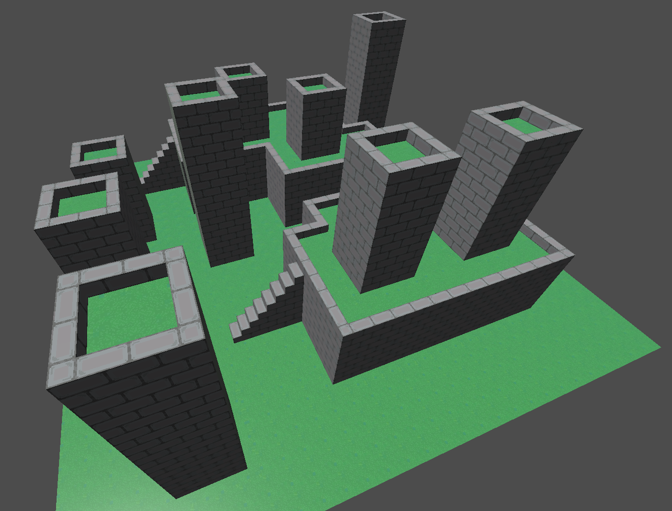
I had created a functional WFC grid generator in Godot using C#. The algorithm worked and that was enough for me. The 20 seconds it took to generate a 20x5x20 grid weren't a problem. Just don't look at the timer! Make a cup of coffee or something while you wait for your level to generate. But, hey! A level with more stairs than usual because I asked for them!
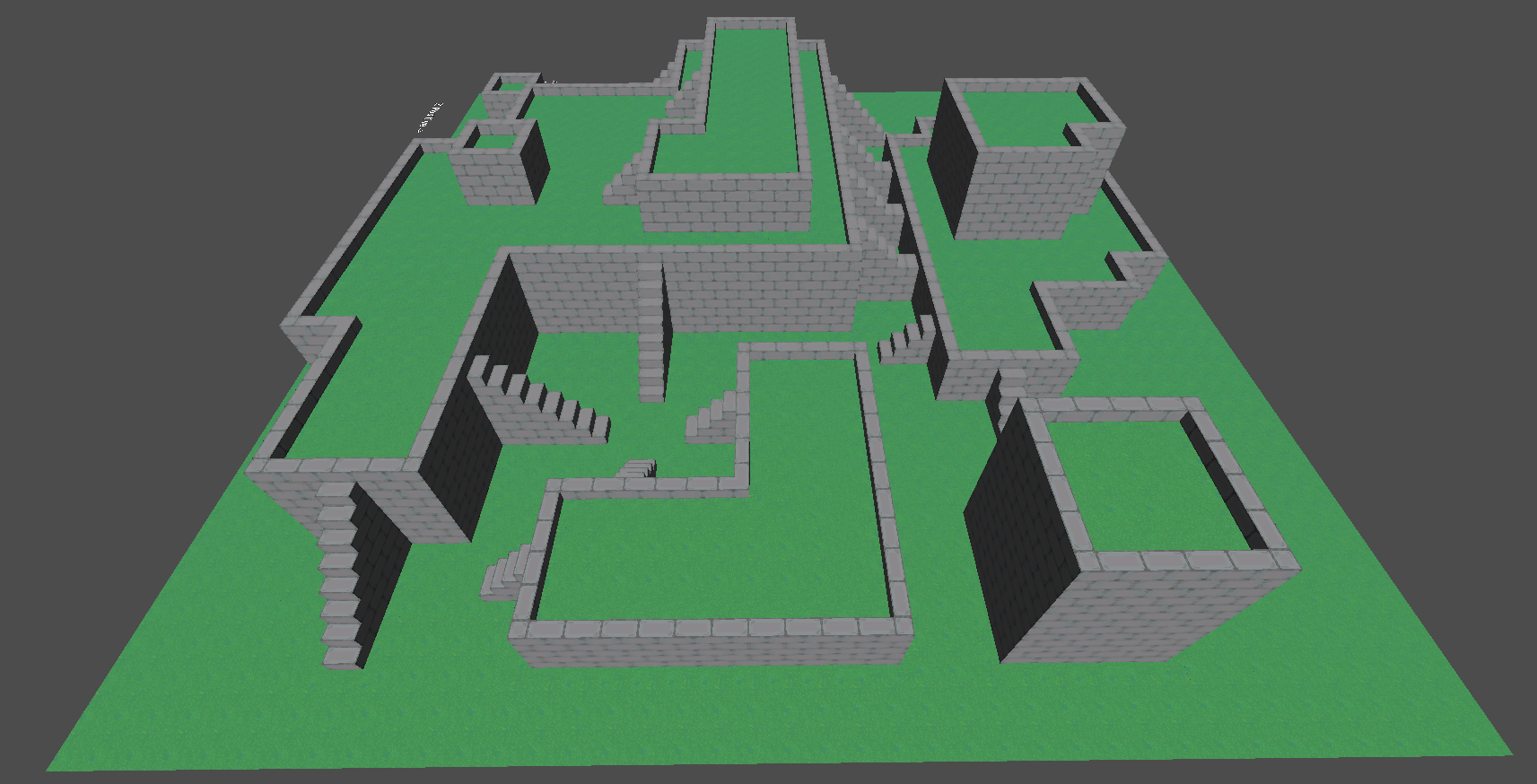
Honestly, looking at this particular tileset, I probably could've gotten away with a 2D WFC implementation and converting that 2D bitmap into a 3D world. Viewing this same world from the top down doesn't really hide much info other than the height of the platforms (which you could just arbitrarily decide on when turning a 2D bitmap into a 3D gridmap):
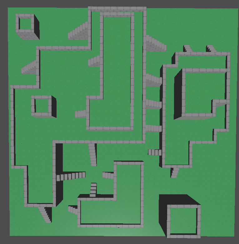 Speaking of gridmaps, I didn't use 'em. I didn't know how to at this point. I just instantiated the meshes in world space. It's funny because the tutorial I watched to help me figure out how to model these pieces was made specifically to help people model for gridmaps. I was already learning so many new things, I didn't want to complicate them further with gridmaps when I was so close to the finish line.
And so, this was the end of a week or so of WFC. It was done. It was functional. And I was done with it... for now.
Intermission: Arc Consistency
Upon taking a break from WFC, I had an idea I wanted to work on that involved fitting colored marbles into slots in a pattern, while preserving some rules about the colors. For example:
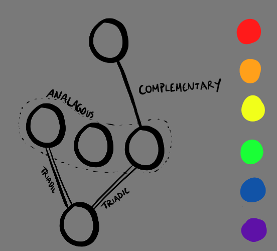 In order to correctly fill in the 5 sockets, you could come up with one of these solutions among many others:
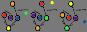
Validating a solution would be simple:
1. Create a graph where the nodes are the slots in the diagram and the edges are the connections between the nodes. The edges would contain data on what type of relationship nodes have with each other.
2. For each node in the graph:
	1. For each edge connected to the node:
		1. Check if the two nodes connected by the edge contain colors that satisfy the relationship specified by the node. If true, continue. If false, return false.
3. If we've made it through the entire graph without returning false, then return true.
A more difficult task would be taking the marbles the user has already slotted in and restricting what is allowed to be placed in the others. What I want is something that achieves the following:
- Start with each slot allowing all possible marbles.
- Place a marble in a slot and restrict the rest of the cells accordingly.
- Continue, etc.
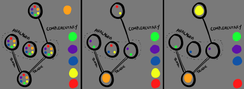
Now, I promise I hadn't come to this problem thinking it would be related to WFC in any way. But here I was propagating constraints again. Only this time I wasn't using a grid; I was using a graph.
I ended up looking into constraint propagation, finding the Arc Consistency algorithm, and implementing it practically 1-to-1. The only things I did differently were:
- Using HashSets instead of arrays to represent the domains of the nodes. That way I could use Intersect() and Union() to combine sets quickly without duplicates.
- Using a Linq Lookup for the graph structure. I was learning about Linq at the time and thought why not apply it.
So here I was having implemented a pretty cool constraint propagation algorithm without many problems, and I thought to myself "What if..."
Act 2: The Gentleman's Approach to Wave Function Collapse
I had seen WFC brought to life by my own hands already. I was in no rush to see it again if it was going to be another Frankenstein's monster of tutorial-sourced patches of code. The name of the game was iterative programming.
Part 1: The GridMap
I was not going to be caught instantiating tile meshes like a clown again. I decided to figure out how the Godot GridMap node worked.
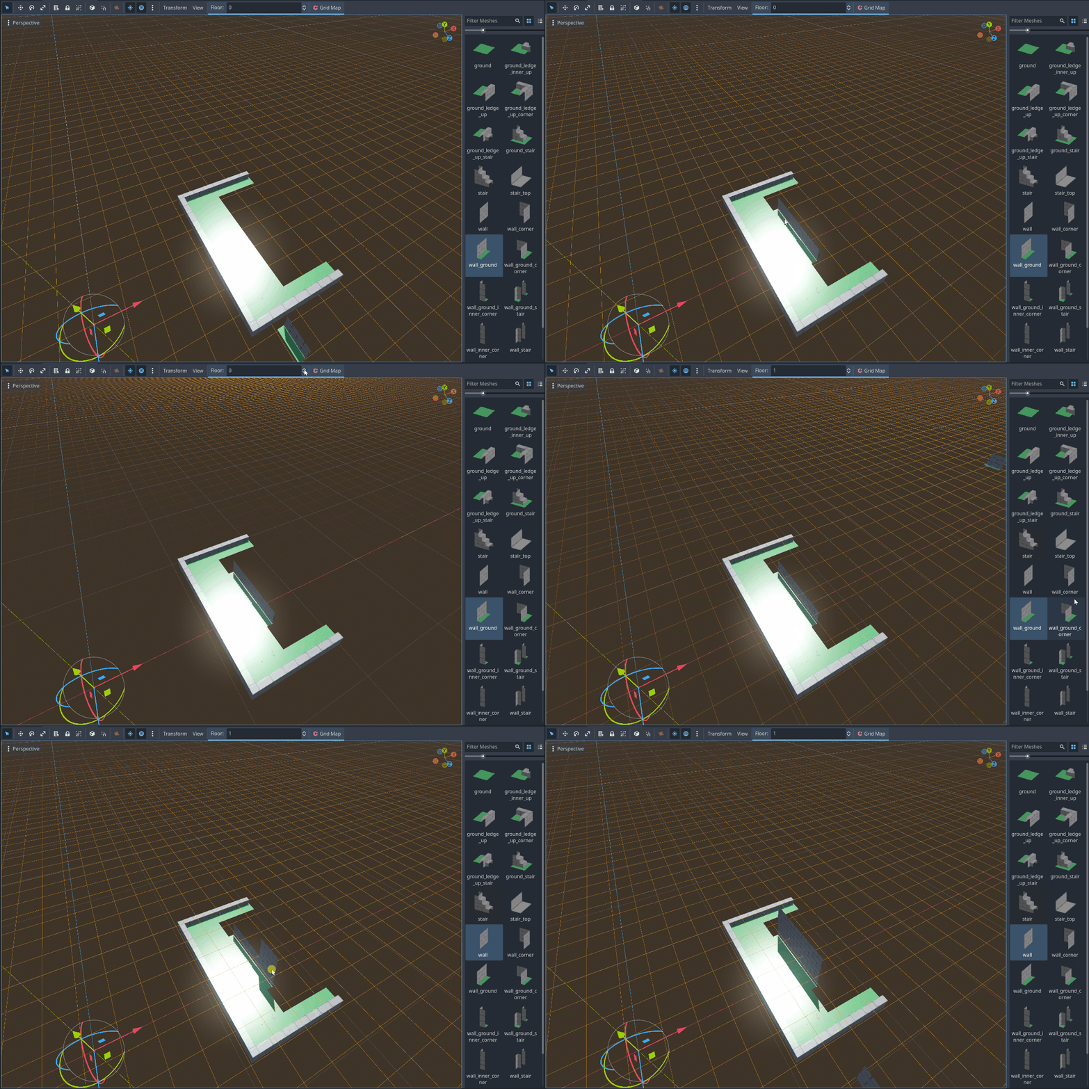 Here I have a scene I have created containing a GridMap node. The GridMap node contains the Mesh Library you can see on the left which allows me to paint nodes into their proper tiles in Godot. Two improvements so far:
- No nodes are being instantiated when I instantiate tiles.
- Tiles rotate in increments of 90 degrees, which is exactly how I stored the rotation value in the Prototype Data JSON!
Unfortunately the JSON data needed a bit more processing before being usable. The MeshLibrary accesses meshes by index, not by name. So I needed to convert the meshName field for each prototype to a meshLibraryIndex field. Nothing Linq couldn't handle.
The more difficult problem was the rotation field. Godot's GridMaps store rotations as integers based on basis matrices. My 0-3 values for rotation didn't match with the rotations I needed, so I need to convert them into radians and create a basis for each of 0, π/2, π, and 3π/2 around the Y axis (I remembered this time >:] ). I then stored the integer rotation values for each basis in an array and used that array to convert from my rotation fields to a Godot-specific orthogonalRotation.
I plopped the mesh and rotation data into a dictionary where the key was the prototype name, and the rest was history. Godot's GridMap.SetCellItem() function takes in a Vector3I for its position, and ints for its tile index and rotation. And yes. Vector3I is a Vector3 using ints instead of floats. I didn't know it existed until this point, and it was a miracle that my Dictionaries using Vector3s didn't run into floating point precision errors.
Part 2: Foreseeing The Omen
This time, I knew what I was up against and decided to be proactive. Here's how you don't have to deal with the differing coordinate systems:
- Open up the prototype data JSON file.
- Godot's vertical axis is the Y axis while Blender's is the Z axis. Using Find and Replace and a temporary string, swap
possibleNeighborsZPoswithpossibleNeighborsYPosandpossibleNeighborsZNegwithpossibleNeighborsYNeg. Your vertical axis is now correctly Y. - The depth axis in Godot (Z) goes in the opposite direction of Blender's Y. Using Find and Replace and a temporary string, swap
possibleNeighborsZPoswithpossibleNeighborsZNegandpossibleNeighborsZNegwithpossibleNeighborsZPos. Your depth axis is now aligned correctly.
Now that that's over, it's time to implement WFC!
Part 3: Setting up the Pieces
I was still going to need a class for the cells in the grid. This time, I used my HashSet technique for storing possible prototypes:
private class WFCCell
{
	private Vector3I _coord;
	private HashSet<string> _initialPossibilities;
	private Dictionary<Vector3I, HashSet<string>>
			_neighborRestrictedPossibilities;
	private HashSet<string> _currentPossibilities;
	private string _collapsedTo;

	public HashSet<string> CurrentPossibilites {get => _currentPossibilities;}
	public string CollapsedTo {get => _collapsedTo;}
	// ...
}
The reason for using the _neighborRestrictedPossibilities dictionary will become clear when I get to propagation.
Next, I needed a class for the arcs, since I wanted to use Arc Consistency to propagate changes.
private class WFCConstraintArc
{
	private Vector3I _startPosition;
	private Vector3I _endPosition;
	private Vector3I _direction;

	public Vector3I Source {get => _startPosition;}
	public Vector3I Destination {get => _endPosition;}

	public WFCConstraintArc(Vector3I startPosition, Vector3I endPosition)
	{
		_startPosition = startPosition;
		_endPosition = endPosition;
		_direction = _endPosition - _startPosition;
	}
	public bool ApplyConstraint(Dictionary<Vector3I, WFCCell> cells,
		Dictionary<string, WFCPrototypeData> prototypeData))
	{
		HashSet<string> possibilities = new HashSet<string>();
		foreach(var possibilePrototype in
			cells[_startPosition].CurrentPossibilites)
		{
			possibilities.UnionWith(prototypeData[possibilePrototype]
				.PossibleNeighbors[_direction]);
		}
		return cells[_endPosition].Restrict(_startPosition, possibilities));
	}
}
An arc is instantiated with a start position and an end position. The magic of an arc happens in the ApplyConstraint() function, which takes in the grid (stored as a dictionary of vectors mapped to cells) and a dictionary mapping names of all possible prototypes to their matching WFCPrototypeData class.
private class WFCPrototypeData
{
	public int Weight {get;}
	public double WeightLogWeight {get;}
	public Dictionary<Vector3I, HashSet<string>> PossibleNeighbors {get;}
	// ...
}
This is a more processed version of the original prototype data class from the prologue. Now the neighbor lists are HashSets mapped from direction vectors. Since arcs store the direction they're taking, they can easily pull the intended set of possible neighbors from the prototype data without an extra function call.
Note the lack of mesh data or rotation data. That's because WFC doesn't care about those values, only the GridMap does.
Part 4: The Grid
Creating the grid is simple:
-
Given a
Vector3I gridSize, create aDictionary<Vector3I, WFCCell> _cellsand populate it with a newWFCCellper position. This will let us reference eachWFCCellobject with its position. -
Create a
List<KeyValuePair<Vector3I, WFCConstraintArc>> arcListwhere we will temporarily create a list of all possible arcs.- Iterate through every position (key) in
_cellsand generate the possible arcs coming from that position in each of the six directions. Add the arcs toarcList. To check if an arc should exist, just check if adding the direction creates a position that exists in_cells.
- Iterate through every position (key) in
-
Turn
arcListinto a Linq Lookup with a simplearcList.ToLookup(e => e.Key, e => e.Value);This will be our graph.
-
Populate a
Queue<WFCConstraintArc> _propagationQueuewith all the arcs inarcListso we can propagate the effects of initial conditions across the grid.
Part 5: Collapsing
Nothing new here. It's just a weighted random selection. I just made sure to set the cell's _currentPossibilities set to only one value: the prototype it collapsed to. This will be important when it comes to...
Part 6: Propagating
The propagation function is genuinely so simple and clean that I can't believe it used to scare me.
public void Propagate()
{
	while(_propagationQueue.Count > 0 && !_contradictionFound)
	{
		WFCConstraintArc currentArc = _propagationQueue.Peek();
		if(currentArc.ApplyConstraint(_cells, _prototypeData))
		{
			// Add arcs from destination point but not going back to this arc's
			// source.
			foreach(var arc in _cellGraph[currentArc.Destination])
			{
				if(arc.Destination != currentArc.Source &&
						!_propagationQueue.Contains(arc))
				{
					_propagationQueue.Enqueue(arc);
				}
			}
		}
		_propagationQueue.Dequeue();
	}
}
Go through each arc in the queue, and apply its constraint. If a change is made to the destination's possibilities, queue the arcs originating from the destination except for the one returning to the current arc's source. It's just arc consistency.
How it determines if a cell has changed goes back all the way to the WFCCell's Restrict() function:
public bool Restrict(Vector3I restrictorCoord, HashSet<string> possibilities)
{
	// Returns true if the restriction made a change
	if(_collapsedTo == null)
	{
		HashSet<string> previousPossibilities =
				_currentPossibilities.ToHashSet();
		_neighborRestrictedPossibilities[restrictorCoord] = possibilities;
		UpdateCurrentPossibilities();
		return !previousPossibilities.SetEquals(_currentPossibilities);
	}
	return false;
}
Note how upon restricting, the function doesn't intersect the incoming possibility set with the one that already exists in the cell. It adds it to _neighborRestrictedPossibilities and mapping to it using the restricting neighbor's coordinates. This way we can keep track of who is creating the changes in the cells.
The UpdateCurrentPossibilities() function does the rest, intersecting all of the restriction sets from the neighbors with the initial possibility set.
public void UpdateCurrentPossibilities()
{
	_currentPossibilities = _initialPossibilities.ToHashSet();
	foreach(var restriction in _neighborRestrictedPossibilities)
	{
		_currentPossibilities.IntersectWith(restriction.Value);
	}
}
Obviously, this introduces overhead. But I have it here as a precautionary measure for if I decide to implement backtracking. Destructively removing possibilities from the set would definitely speed things up even more, as this adds a bunch of set operations per step of the propagation.
With collapsing and propagating out of the way, all that was left was figuring out how to select the next piece... You know what that means.
Part 7: Facing Entropy
Let's take a look at the scary equation. Entropy is defined on its Wikipedia page as:
I deciphered these arcane runes to something more resembling programming terms I find easier to read.
If the event we are observing has possible outcomes and each outcome has a probability of of occurring, then entropy is
or
Cool. I could work with that. Unfortunately, I was using weights instead of probabilities, so there were more conversions to do:
Let's say (the sum of all weights) and our formula becomes simplified to
If you plug this into the entropy formula and do some logarithm magic, you get
And this is why I stored a double WeightLogWeight in my prototype data class. Since I was going to be using it a lot, might as well pre-calculate it. By the way, entropy logarithms use whatever base you like as long as its consistent. I used 2.
It's wild how not scary the math is when I'm taking my time instead of trying to just get something to work quickly. In fact, while writing this devlog, I actually realized that if all the probabilities or weights are the same (so for all ), you get an interesting result:
It turns out this is why I had used the number of possibilities as the entropy back before weights were introduced. The logarithm doesn't need to be there because goes up as goes up.
Anyway, to use this, I just did a linear scan of all the remaining cells, calculating their entropy to figure out which cell had the least entropy. That cell would be selected to be collapsed.
Part 8: Contradictions
Sometimes WFC will run into contradictions. It just happens. A contradiction occurs when a cell's possibility set is fully emptied. So I made a simple edit to this function
public bool UpdateCurrentPossibilities()
{
	// Returns false if contradiction
	_currentPossibilities = _initialPossibilities.ToHashSet();
	foreach(var restriction in _neighborRestrictedPossibilities)
	{
		_currentPossibilities.IntersectWith(restriction.Value);
	}
	if(_currentPossibilities.Count == 0)
	{
		GD.Print("Contradiction");
		return false;
	}
	else
	{
		return true;
	}
}
making it return true if we were good to go or false if a contradiction occured. Yes, I know I could've just used return _currentPossibilities.Count != 0; instead of the if-else chain. I wanted a print statement. Get off my back.
Instead of dealing with backtracking or contradiction solving right now, I opted to just stop the algorithm when a contradiction was found and display the partially solved grid like so:
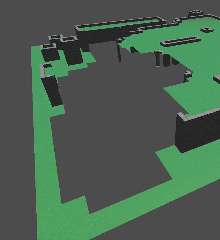 Which leads me to:
Part 9: It works... Significantly Faster!
I did a little analysis on the time it took for this algorithm (dubbed ArcConWFC) and compared it to the previous attempt (dubbed plainWFC) and here's what I got:
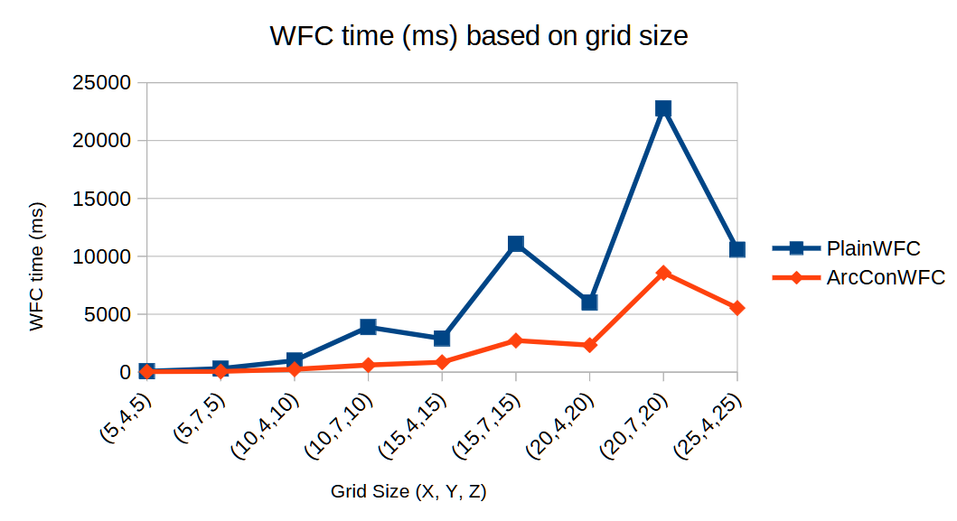 Now, something here confused me. Why did the time go up from 15x4x15 (900 cells) to 15x7x15 (1575 tiles) but then back down when going to 20x4x20 (1600 tiles). And why did this happen multiple times with different extremities? Well, it took me a second, but I remembered Arc Consistency's time complexity was where was the number of arcs. The number of cells was related to the number of arcs, but the positioning of the cells also mattered. You'd have less arcs on a flatter map than you would in a cube of the same area. Turns out, I was right.
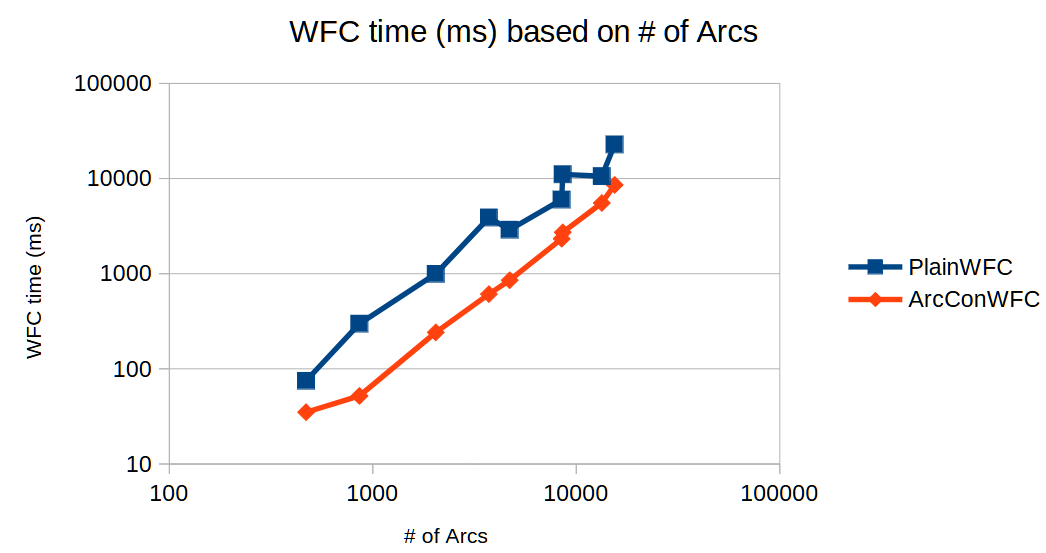 I have no clue why plainWFC reacted to taller grids the way it did, but honestly, I'm just happy Arc Consistency was faster than my original Madman's attempt.
Stay tuned for Act 3: Dealing with Contradictions.